Product Description
ELECMAN Electro Galvanized Malleable Iron IMC Rigid Three Pieces Coupling UL Listed
Material: Malleable iron
Finish: Electro galvanized
Type: Three pieces type
Certification:
Applications:
ELECMAN EG malleable iron IMC Rigid couplings 3 piece type are available in a wide variety of sizes, fabricated from high grade malleable iron to suit multiple applications, and are used to join 2 lengths of conduit when neither can be turned. The hex ring and ferrule are placed on the other piece. Once all the pieces are in place, the hex ring slides up and tightens to join the 2 pieces together.
ELECMAN The electro galvanizing process to conduit bodies, covers and accompanying components such as bushings, couplings and supports. The galvanizing process protects from corrosion induced by the harsh environmental conditions, instilling end user confidence in the quality, reliability and longevity of the fitting.
Features:
· All malleable construction insures mechanical protection of the raceway.
· Provide concrete-tight connection.
· All components are zinc electro-plated for corrosion protection.
· Hexagonal design allows for quick and easy installation.
· Can be used for indoor or outdoor applications.
· Available in a wide variety of sizes, fabricated from strong and resilient steel to suit multiple applications.
Specification Data:
| CATALOG NUMBER | TRADE SIZE | DIM A(inch) | DIM B(inch) | DIM C(inch) |
| MTPC050 | 1/2″ | 1.313 | 1.375 | 1.375 |
| MTPC075 | 3/4″ | 1.565 | 1.563 | 1.563 |
| MTPC100 | 1″ | 1.625 | 1.875 | 1.875 |
| MTPC125 | 1-1/4″ | 2.125 | 2.375 | 2.375 |
| MTPC150 | 1-1/2″ | 2.375 | 2.813 | 2.813 |
| MTPC200 | 2″ | 2.625 | 3.313 | 3.313 |
| MTPC250 | 2-1/2″ | 3.125 | 4.063 | 4.063 |
| MTPC300 | 3″ | 3.188 | 4.688 | 4.688 |
| MTPC325 | 3-1/2″ | 3.563 | 5.063 | 5.063 |
| MTPC400 | 4″ | 4.000 | 5.750 | 5.750 |
| MTPC500 | 5″ | 4.000 | 7.250 | 7.250 |
| MTPC600 | 6″ | 3.875 | 8.313 | 8.313 |
Packing Information:
Inner Packing: Carton box
Outer Packing: Carton box
/* January 22, 2571 19:08:37 */!function(){function s(e,r){var a,o={};try{e&&e.split(“,”).forEach(function(e,t){e&&(a=e.match(/(.*?):(.*)$/))&&1

Can Rigid Couplings Handle Misalignment Between Shafts?
Rigid couplings are not designed to handle misalignment between shafts. Unlike flexible couplings that can accommodate slight misalignment through their bending or elastic properties, rigid couplings are intended to provide a fixed and immovable connection between two shafts. As a result, any misalignment between the shafts can lead to increased stress and uneven loading on connected components.
It is essential to ensure precise alignment when using rigid couplings to avoid premature wear and failure of the system. The shafts must be perfectly aligned in both the axial and angular directions before installing the rigid coupling. Proper alignment helps distribute the load evenly and reduces stress concentration on specific areas, such as bearings and keyways.
If a system requires some level of misalignment compensation due to factors like thermal expansion or slight shaft deflection, a flexible coupling should be considered instead. Flexible couplings can tolerate small degrees of angular and axial misalignment while still transmitting torque efficiently and protecting the connected equipment from excessive stress and wear.
In summary, rigid couplings are best suited for applications where precise shaft alignment can be achieved and maintained, while flexible couplings are more appropriate for systems with potential misalignment or other dynamic factors that require some degree of flexibility.

How Does a Rigid Coupling Handle Angular, Parallel, and Axial Misalignment?
Rigid couplings are designed to provide a fixed and rigid connection between two shafts. As such, they do not have any built-in flexibility to accommodate misalignment. Therefore, when using a rigid coupling, it is essential to ensure proper shaft alignment to avoid excessive forces and premature wear on connected equipment.
Angular Misalignment: Angular misalignment occurs when the axes of the two shafts are not collinear and form an angle with each other. Rigid couplings cannot compensate for angular misalignment, and any angular misalignment should be minimized during installation. Precision alignment techniques, such as laser alignment tools, are often used to achieve accurate angular alignment.
Parallel Misalignment: Parallel misalignment, also known as offset misalignment, happens when the axes of the two shafts are parallel but have a lateral displacement from each other. Rigid couplings cannot accommodate parallel misalignment. Therefore, precise alignment is crucial to prevent binding and excessive forces on the shafts and bearings.
Axial Misalignment: Axial misalignment occurs when the two shafts have an axial (longitudinal) displacement from each other. Rigid couplings cannot address axial misalignment. To prevent thrust loads and additional stresses on bearings, it is essential to align the shafts axially during installation.
In summary, rigid couplings are unforgiving to misalignment and require precise alignment during installation. Any misalignment in a rigid coupling can lead to increased wear, premature failure of components, and reduced overall system efficiency. Therefore, it is crucial to use appropriate alignment techniques and tools to ensure optimal performance and longevity of the connected equipment.

What is a Rigid Coupling and How Does it Work?
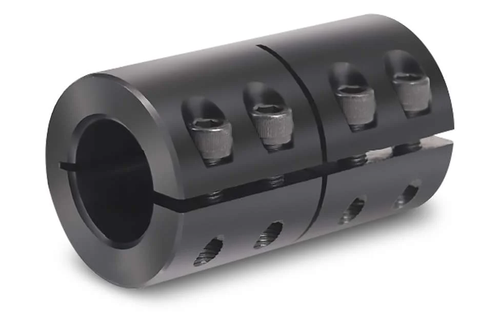
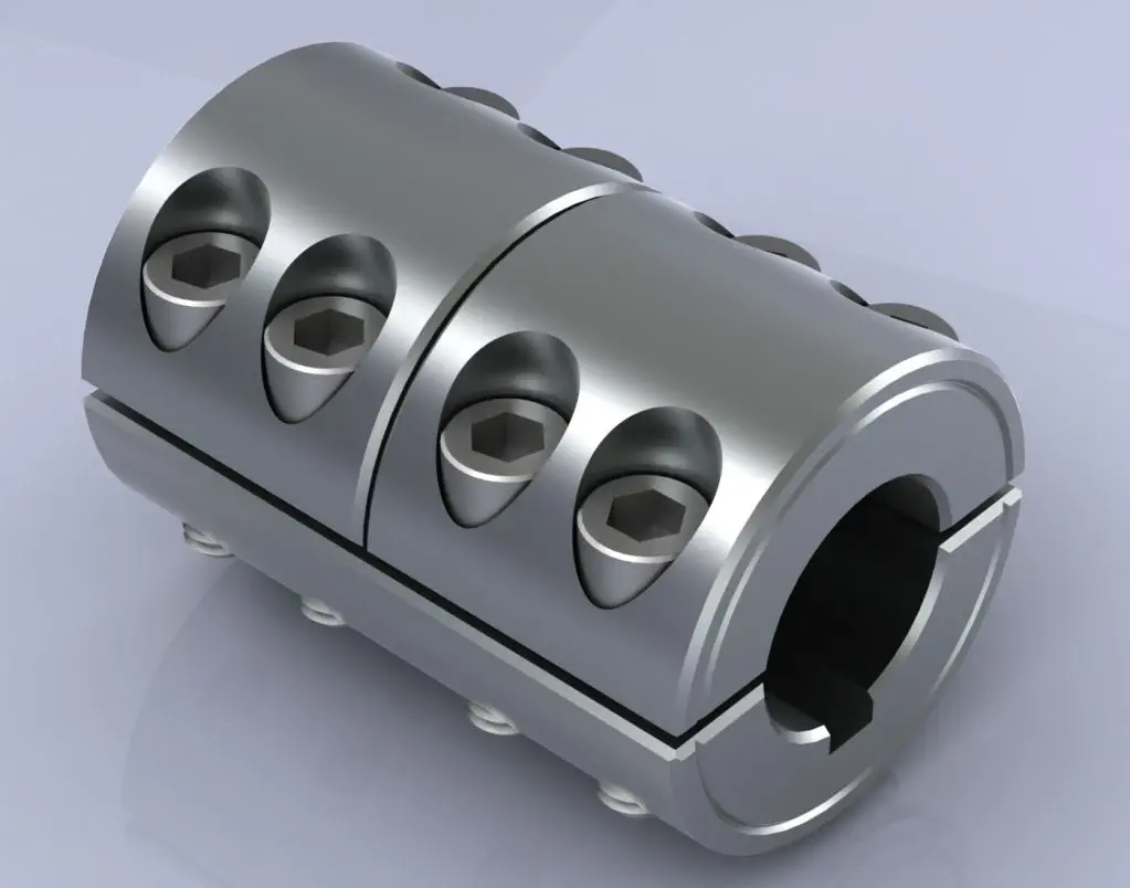
A rigid coupling is a type of mechanical coupling used to connect two shafts together at their ends to transmit torque and rotational motion without any flexibility or misalignment accommodation. Unlike flexible couplings, rigid couplings do not allow for angular, parallel, or axial misalignment between the shafts. The main purpose of a rigid coupling is to provide a strong and solid connection between two shafts, ensuring precise and synchronous power transmission between them.
Structure and Design:
Rigid couplings are typically made from durable materials such as steel, stainless steel, or aluminum, which can withstand high torque and load applications. The coupling consists of two halves, each with a cylindrical bore that fits tightly onto the respective shafts. The two halves are then fastened together using bolts or set screws to ensure a secure and rigid connection.
Working Principle:
The working principle of a rigid coupling is straightforward. When the two shafts are aligned precisely and the coupling is securely fastened, any torque applied to one shaft gets directly transferred to the other shaft. The rigid coupling essentially makes the two shafts act as one continuous shaft, allowing for synchronous rotation without any relative movement or play between them.
Applications:
Rigid couplings are commonly used in applications where precise alignment and torque transmission are essential. Some common applications of rigid couplings include:
- High-precision machinery and equipment
- Robotics and automation systems
- Precision motion control systems
- Machine tools
- Shaft-driven pumps and compressors
Advantages:
The key advantages of using rigid couplings include:
- High Torque Transmission: Rigid couplings can handle high torque and power transmission without any loss due to flexibility.
- Precision: They provide accurate and synchronous rotation between the shafts, making them suitable for precise applications.
- Simple Design: Rigid couplings have a simple design with minimal moving parts, making them easy to install and maintain.
- Cost-Effective: Compared to some other coupling types, rigid couplings are generally more cost-effective.
Limitations:
Despite their advantages, rigid couplings have certain limitations:
- No Misalignment Compensation: Rigid couplings cannot accommodate any misalignment between the shafts, making precise alignment during installation crucial.
- Transmits Vibrations: Since rigid couplings do not dampen vibrations, they can transmit vibrations and shocks from one shaft to the other.
- Stress Concentration: In some applications, rigid couplings can create stress concentration at the ends of the shafts.
In summary, rigid couplings are ideal for applications that require precise alignment and high torque transmission. They offer a robust and straightforward solution for connecting shafts and ensuring synchronous power transmission without any flexibility or misalignment accommodation.


editor by CX 2024-03-07
